
A Programmable Logic Controller (PLC) accepts inputs from a variety of devices such as switches, sensors etc., processes inputs according to user programmed control logic, and controls a variety of devices (e.g. relay, motors, valves etc.) connected to the outputs of the PLC. The Relay Ladder Logic is the user programmed control algorithm.
Relay Ladder Logic is one of the international standards and is the main programming method used to program PLC’s. It mimics the relay logic (combination of switches, relays, coils and contacts). The decision to use ladder logic as the main programming method was very strategic as it did not need much time to retrain engineers to adapt to this. The first generation PLCs were programmed with a technique that was based on relay logic wiring schematics. This eliminated the need to teach electricians, maintenance technicians and engineers how to program. To this day, it remains the most popular method to program a PLC.
Below is a very simple motor control relay logic and it’s corresponding ladder logic. Relay Logic has a Start switch, Stop switch, Control Relay, Relay Coil (CR1) and a Motor (Mtr). Ladder logic shares similar look and feel of relay logic. But the physical switches and coils of relay logic are replaced with PLC’s memory location which are represented as Inputs (I) and Outputs (O) in ladder logic.
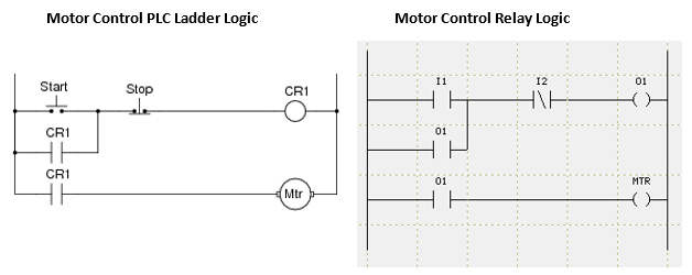
Typically the PLC CPU scans the ladder from top left to bottom right and reads and executes the condition of physical I/O’s. The time taken to make one pass from top to bottom and execute logic is known as scan time.
A PLC system handles many numbers representing different types of information regarding the process. These process/machine parameters may be anything from the status of the input or output devices, timers/counters, or other data values. Each PLC manufacturer has their own conventions for this in their PLCs. These memory types can be used to store a variety of information and can be used inside various Relay Ladder Logic instructions.
A Discrete memory type is one bit that can be either a 1 or a 0 (ON or OFF). Discrete memory area is used for inputs, outputs, control relays, and timer/counter bits.
A Word memory type is a 16-bit location that is normally used to store and manipulate numeric or ASCII data. A word memory location is also called a Register.
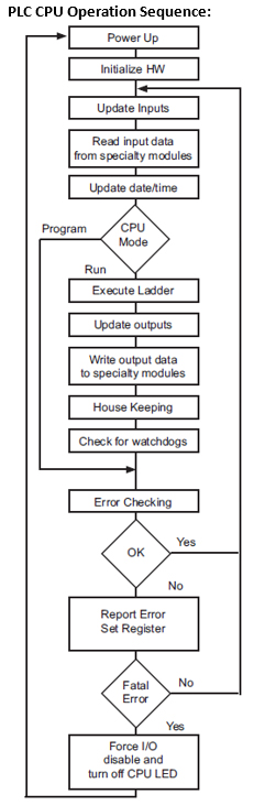
Power-up Initialization
At power-up, the CPU initializes the internal electronic hardware. It also checks if all the memories are intact and the system bus is operational. It sets up all the communication registers. It checks the status of the backup battery. If all registers are go, the CPU begins its cyclic scan activity as described below.
Read Inputs: The CPU reads the status of all inputs, and stores them in an image table. IMAGE TABLE is PLC’s internal storage location where it stores all the values of inputs/outputs for ONE scan while it is executing ladder logic. CPU uses this image table data when it solves the application logic program. After the CPU has read all the inputs from input modules, it reads any input point data from the Specialty modules like High Speed Counters.
Execute Logic Program: This segment is also called Ladder Scan. The CPU evaluates and executes each instruction in the logic program during the ladder scan cycle. The rungs of a ladder program are made with instructions that define the relationship between system inputs and outputs. The CPU starts scanning the first rung of the ladder program, solving the instructions from left to right. It continues, rung by rung, until it solves the last rung in the main logic. At this point, a new image table for the outputs is updated.
Write Outputs: After the CPU has solved the entire logic program, it updates the output image table. The contents of this output image table are written to the corresponding output points in I/O Modules. After the CPU has updated all discrete outputs, it scans for the specialty modules. The output point information is sent to the specialty I/O like High Speed Counters.
Immediate Inputs/Outputs: There is a possibility that an input changes after the CPU has read or scanned the inputs. If you have an application that cannot wait until the CPU returns for the next input scan, you can use Immediate Instructions.
These instructions do not use the status of the input from the image table to solve the application program. The Immediate instructions immediately read the input status directly from I/O modules and update the Input table with appropriate status of input module read. Similarly, Immediate Output instructions do not wait for the CPU to complete the ladder scan. Immediate outputs are directly written to the image table and Outputs are updated accordingly.
Subroutines: The CPU executes subroutines when called for in the ladder program. These subroutines are useful in performing the same logic operation time and time again just upon one call so you do not have to repeat the rung logic over and over again. Subroutines are also useful in executing a logical function, for example check limits, upon receiving an external interrupt from a PLC I/O module.
I/O response time is typically defined as the time required for the control system to note a change in an input point and update a corresponding output point. In majority of the applications, the processor of a PLC responds practically instantaneously to this task. There are some applications that require extremely fast I/O scan times. The following four factors affect the I/O response time of a CPU:
1. The point in the scan period when the field input changes its state.
2. Delay time for Input module to change state.
3. CPU scan time.
4. Delay time for Output module to change state.

See the diagram above. The I/O response time is minimum when the I/O module gets the input change before the Read Inputs portion of the Ladder execution scan cycle. In this case the input status is read, the logic program is solved, and the corresponding output point gets updated. The total I/O response time is calculated as:
I/O Response = Delay in Input module + CPU Scan Time + Delay in Output module
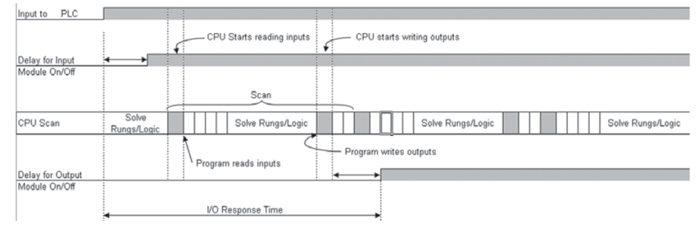
The I/O response time is maximum when the I/O module notes an input change after the Read Inputs portion of the Ladder execution scan cycle. In this case the input status gets noted only in the following Input scan. The diagram shows an example of I/O response timing for this condition. The total I/O response time is calculated as:
I/O Response = Delay in Input module + 2 times the CPU Scan Time + delay in output module
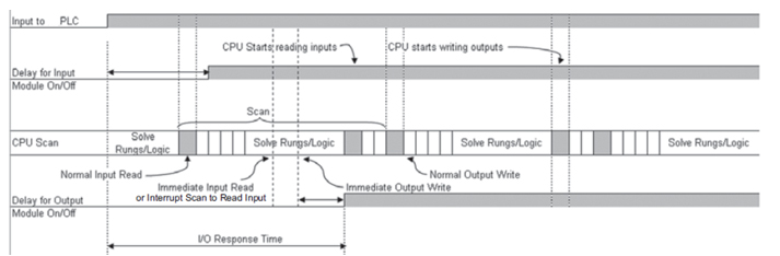
Using Interrupt subroutines and Immediate I/O instructions is the best way to optimize the I/O Response time of your PLC system. The immediate instructions update the I/O points during the ladder logic program execution.
The diagram shows how immediate input and output instructions affect the I/O response timing.
The total I/O response time is simply calculated as: I/O Response = Delay in Input module + Instruction Execution Time + Delay in Output module + Instruction Execution Time = Immediate Input Instruction Execution + Immediate Output Instruction + Time for Execution of all Instructions in between.
The total I/O response time for an external interrupt and a subroutine is calculated as:
Delay in Input Module + execution of subroutine + delay in output module.
As an example, upon an interrupt you can read the status of an input bit, perform a logical operation on it based upon the value of some other registers, and turn on an output in less than 50μs.
CPU Scan Time Considerations:
The scan time includes all the tasks that are performed by the operating system in a cyclic manner. As discussed previously, each scan cycle is made up of several segments. Each of these segments takes a certain amount of time to execute. Among all the segments, the amount of time it takes to execute the application program is the only one that has maximum influence on total scan time. This also happens to be the one segment you can control as a user. If your application needs a smaller scan time, then you should try to choose instructions with as fast execution time as possible. This is because different instructions take different amounts of time to execute. Your choice of I/O modules and system configuration can also affect the scan time.
Conclusion: If you are new to Relay Ladder Logic Programming, here is a sequence you should follow to develop Relay Ladder Logic program.